Introduction to Unity Shader Graph (Unity Shader Notes)
Shaders are one of the bases of 3D Art, and when it comes to game engine, it an almost mandatory skill to at least know for some specific tasks, some of them involved directly with 3D modeling, VFX, and, mainly, Materials
The mission
- Learn the base of Shaders, in this case for Shadergraph.
- Understand those bases to apply them to different situations, understanding what we doing and not depending fully on video tutorials.
- Expand our explorations capabilities with software used.
Resources
- Unity (Preferably 2021 onwards).
- Unreal Engine (Preferably 5).
Introduction
The language of Shaders is math, and it is important to understand them for a better capability of abstraction when it comes to making visual effects with shaders or particles.
Creating a Shadergraph
In this case we are gonna work with Unity Shadergraph, but, as it is very similar to Unreal. Engine shader sistem, you could also extrapolate it to Unreal Engine.
First of all we´ll open the Spatial SDK project. Which is made in the “Universal Render Pipeline” of Unity. This is important, as it will directly affect to the posibilities this tool brings us.
To create a ShaderGraph that is compatible with URP and Built-In, we are gonna follow this steps:
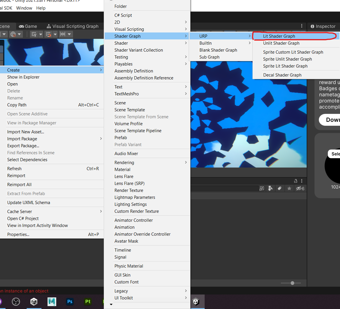
For shaders use always the naming the following way: “assetname”_Sh
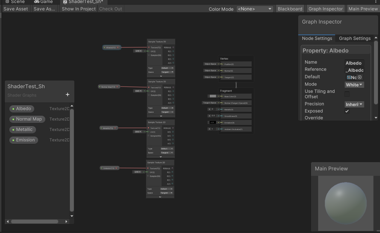
Once creates, we should have an Icon like this in our project browser. This is not a material, but the logic behind it that will allow us to put in the material, for example, the base color, the normal map, maks or effects of all kinds on it.
Inside the Shader
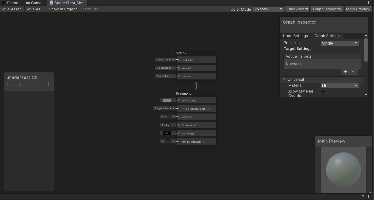
Once we open the Shader, we should be seeing a workspace like this:
You can modify distribution as you find it more comfortable
Graph Inspector
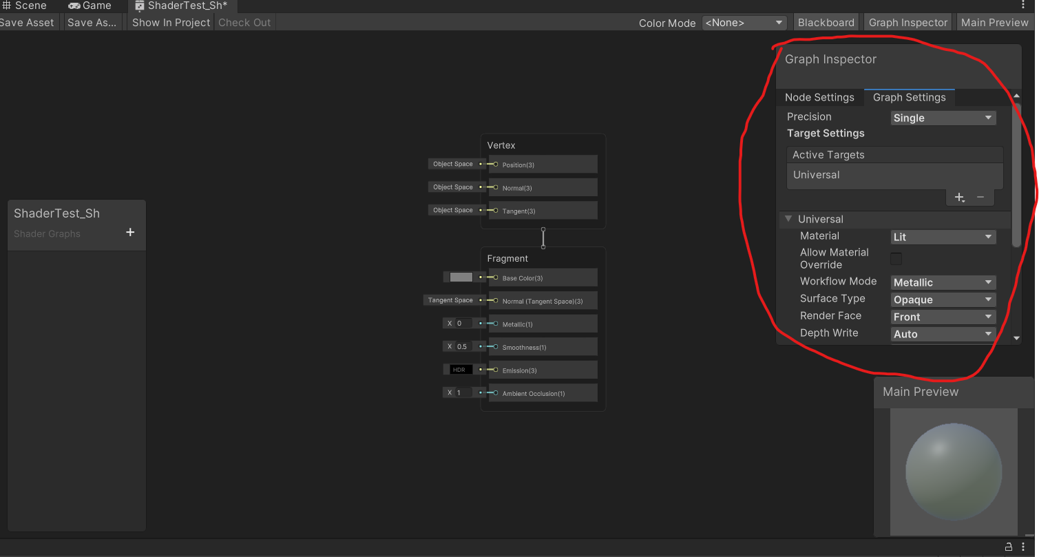
This window will show and allow us to edit parameters for the entire shader or for specific nodes.
Graph settings
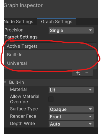
This tab will get us to the general settings of the shader, for example:
- Defining the target render pipeline of the shader (URP, Built-In or Both).
In this case we are gonna use it only for Universal Render Pipeline.
As you can see, there´s a “precision” button on the top of the material. Don´t touch it, don´t change it.
You can also change other parameters, like making it “lit” or “unlit”, changing from opaque to transparent and enabling or disabling alpha clipping, depending if you want to make a surface material, a fade, or a cutout.
Parameter window
In this place is where you will declare all the variables that you want to be visible on the material. You can also hide them, but this is built merely for public variables.
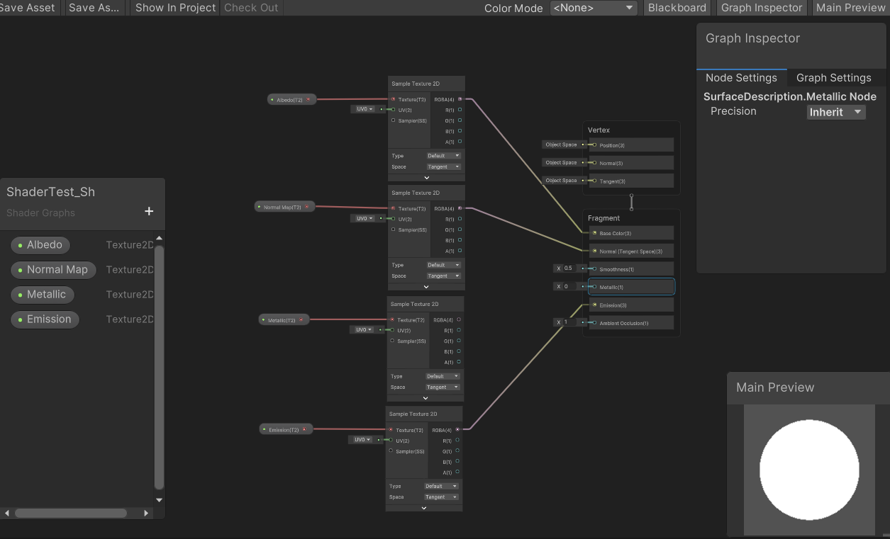
Input and preview
These are the input nodes for our materials. They will change depending on which kind of materials or nodes we want to use.
“Vertex” take information from object model and allow us to modify its geometry.
Example:
“Fragment” nodes allow us to modify color, masks and surface texture parameters. Making gradients, pann UV textures, create cutout or fade masks.
Example:
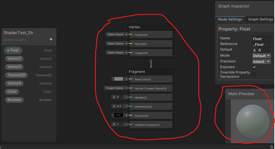
Parameters/variables
We learned about the parameter window earlier. Now we are gonna see what are these parameters and how do they work.
Float and vectors
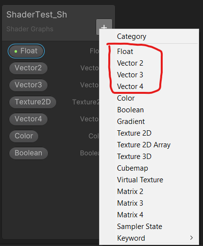
They are the most basic variables for making modifications, or parameters in our Shaders/materials.
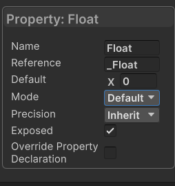
Float = Vector 1. It is a number. This number can be any unless you modify its parameters on the Node inspector to have a minimum and a maximum.
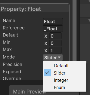
This number can be any unless you modify its parameters on the Node inspector to have a minimum and a maximum
You can try to drag and drop the variable from the parameter window to the graph and connect it to different inputs and see in real time how it affects to your material.
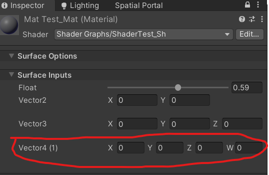
Vector 2, 3 and 4 are similar to floats, but they contain more info. For example:
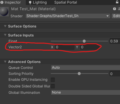
- Vector 2 contains 2 integers, defined as X and Y. you can use it for tiling different edges on your textures.
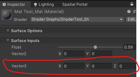
- Vector 3 contains instead 3 parameters inside. Example: you can use it to modify parameters on the R, G and B channel of a texture, all in the same parameter.
- Vector 4 contains 4 parameters. Example: modifying R, G B and Alpha channels on a texture, or accesing quadrant parameters on a texture.
Color
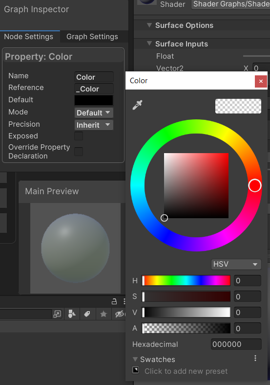
This node is, as it says, a color, which is basically a Vector 3. Unity created this node to ease technical artists work when defining color parameters inside shaders instead of using number ranges from 0 to 255.
Texture 2D
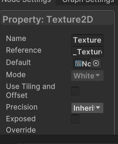
This allows you to define specific texture nodes. For example: albedo, normal maps, metallic, etc…
You can add tiling and offset to each one of them, but I recommend to make it global inside shader.
The rest of the parameters will be barely used in general materials, so we are gonna enter
Practice example: making a simple base shader for your material
We are gonna make an opaque shader for basic surface materials step by step. It will be a PBR material. So we will use 3 textures + emission.
Create as many parameters as textures will have your material.
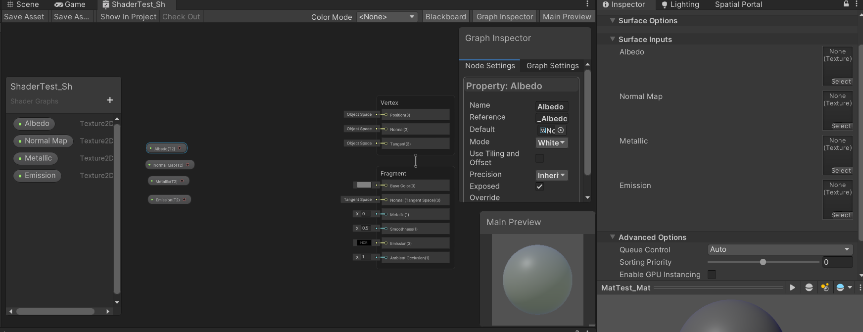
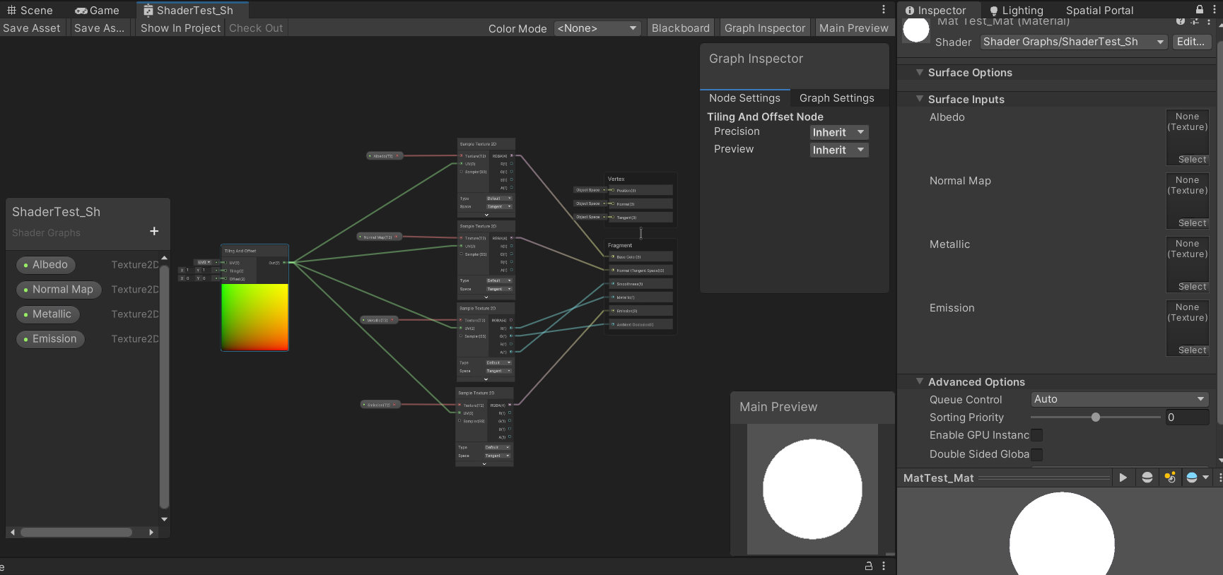
Instead of connecting nodes direcly to each texture input, we are gonna put a “SampleTexture2D” for each texture parameter we have. To make this, press space with your cursor on the shader graph and search for “SampleTexture2D”.
Connect each parameter to the “Texture(T2)” input of each sampled texture 2D. This node allow us to modify texture UVs and RGBA channels if needed.
Next we gonna connect each texture “RGBA” node to its correspondent input, LESS THE METALLIC.
DISCLAIMER: CTRL + S on each important action. So you can see the progress on the material in the inspector.
Metallic textures in Unity distributes the channels the following way:
- Red Channel : metallic.
- Green Channel: ambient occlusion.
- Blue Channel: none. You can use this channel for a mask or an alpha if you need.
- Alpha Channel: smoothness.
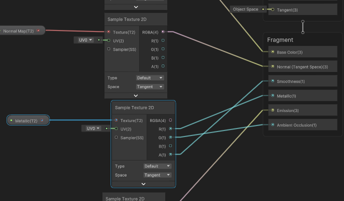
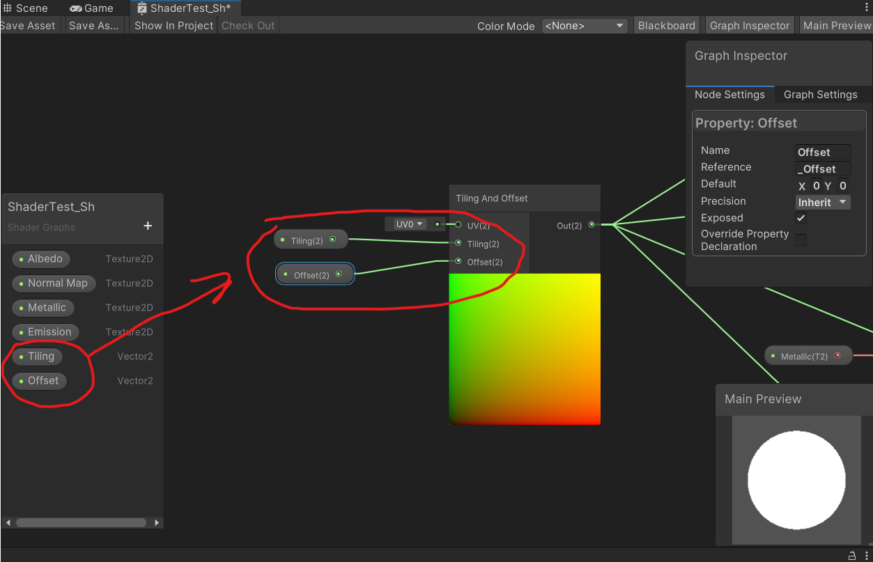
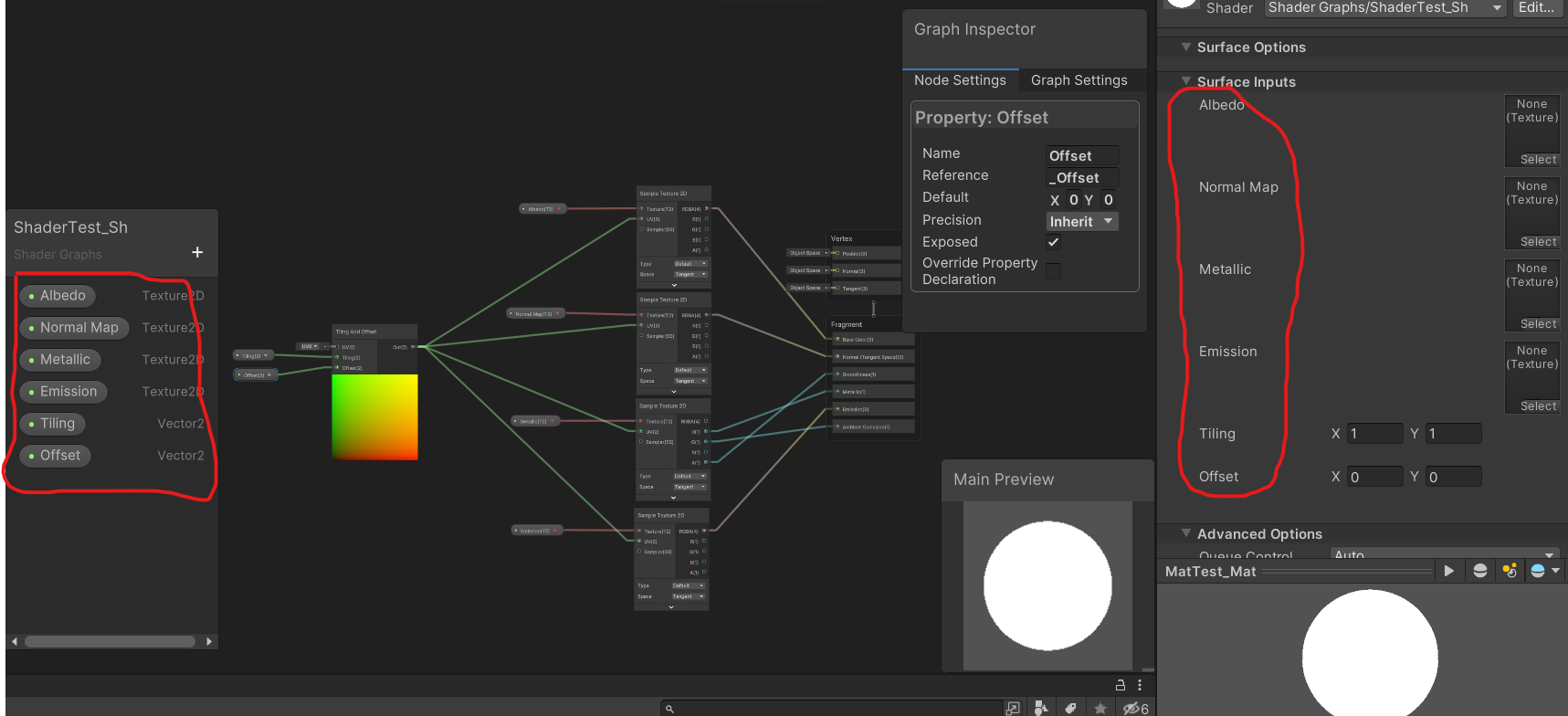
Now we are going to make all the textures globaly tileables, instead of adding a parameter for each one of them.
First of all, we´ll add a “Tiling and Offset” node to the graph.
Next, we connect “Out(2)” to the “UV(2)” of each texture, which is, as we can see, the UV modifier of the texture.
We see something like this, but we can´t see the tiling and offset modifiers on the material yet. For that we are gonna create 2 Vectors 2, one for tiling and another one for the offset, and connect them to their correspondent inputs.
Remember to make your tiling vector default values equal to 1 on X and Y or you won´t see your texture on your material.
With this we have our basic PBR material built. If you want to order parameters on the material just drag and drop up and down on the paremeter window and save the shader so you will see your parameters appear the same way they are ordered in the parameter window.
Same would be for cutout and fade materials, but using and connecting opacity to its correspondent node. In this case, opacity usually goes in the alpha channel of the albedo texture, unless you want a custom map to play with.
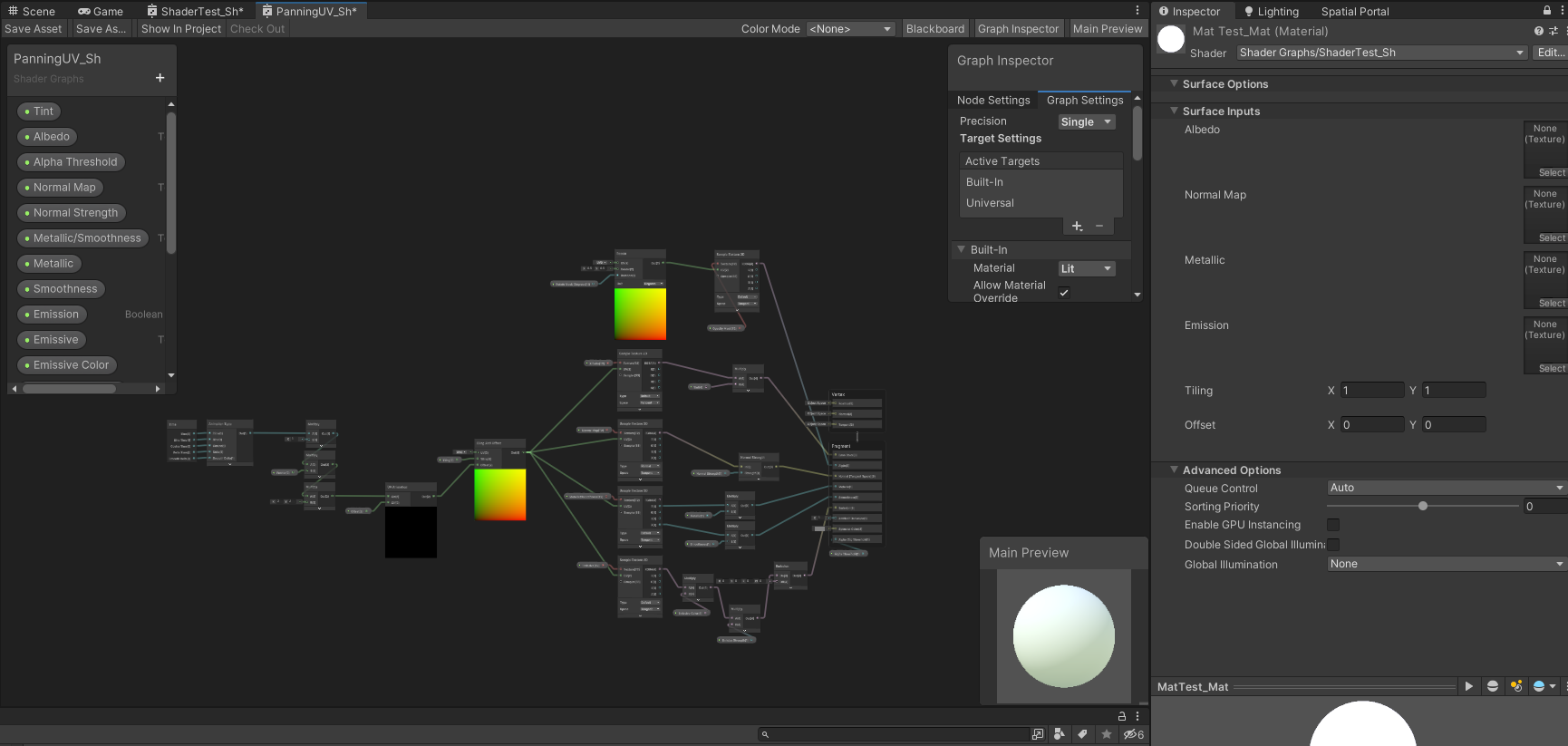
Example of a more complex material that animates UVs to pann textures and make an animation.